Types of hydraulic pump
There are typically three types of hydraulic pump constructions found in mobile hydraulic applications. These include gear, piston, and vane; however, there are also clutch pumps, dump pumps, and pumps for refuse vehicles such as dry valve pumps and Muncie Power Products’ Live PakTM.
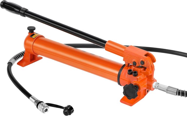
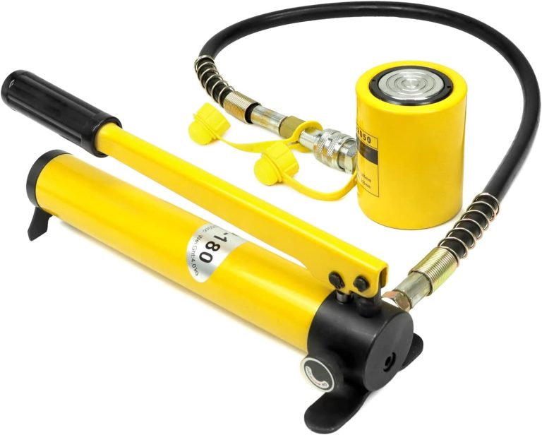
The hydraulic pump is the component of the hydraulic system that takes mechanical energy and converts it into fluid energy in the form of oil flow. This mechanical energy is taken from what is called the prime mover (a turning force) such as the power take-off or directly from the truck engine.
With each hydraulic pump, the pump will be of either a uni-rotational or bi-rotational design. As its name implies, a uni-rotational pump is designed to operate in one direction of shaft rotation. On the other hand, a bi-rotational pump has the ability to operate in either direction.
 GEAR PUMPS
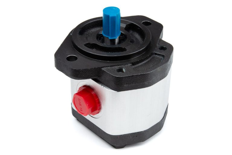
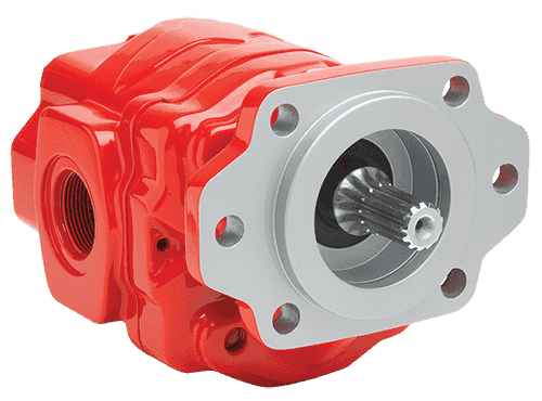
For truck-mounted hydraulic systems, the most common design in use is the gear pump. This design is characterized as having fewer moving parts, being easy to service, more tolerant of contamination than other designs, and being relatively inexpensive. Gear pumps are fixed displacement, also called positive displacement, pumps. This means the same volume of flow is produced with each rotation of the pump’s shaft. Gear pumps are rated in terms of the pump’s maximum pressure rating, cubic inch displacement, and maximum input speed limitation.
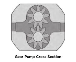
Generally, gear pumps are used in open center hydraulic systems. Gear pumps trap oil in the areas between the teeth of the pump’s two gears and the body of the pump, transport it around the circumference of the gear cavity, and then force it through the outlet port as the gears mesh. Behind the brass alloy thrust plates, or wear plates, a small amount of pressurized oil pushes the plates tightly against the gear ends to improve pump efficiency.
 QUICK LOOK
- Most common design
- Fewer moving parts, easy to service, more tolerant of contaminants, relatively inexpensive
- Fixed, also called positive displacement pumps
- Rated in terms of maximum pressure rating, cubic inch displacement, maximum input speed limitation
- Used in open center hydraulic systems
- Transports oil around the circumference of the gear cavity and forces it through the outlet port
- Encompasses thrust plates that push against gear ends with a small amount of pressurized oil to improve pump efficiency
PISTON PUMPS
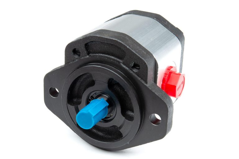
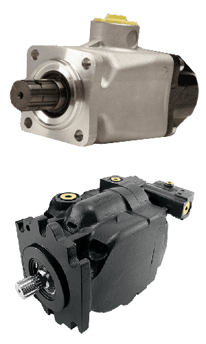 When high operating pressures are required, piston pumps are often used. Piston pumps will traditionally withstand higher pressures than gear pumps with comparable displacements; however, there is a higher initial cost associated with piston pumps as well as a lower resistance to contamination and increased complexity. This complexity falls to the equipment designer and service technician to understand to ensure the piston pump is working correctly with its additional moving parts, stricter filtration requirements, and closer tolerances. Piston pumps are often used with truck-mounted cranes, but are also found within other applications such as snow and ice control where it may be desirable to vary system flow without varying engine speed.
A cylinder block containing pistons that move in and out is housed within a piston pump. It’s the movement of these pistons that draw oil from the supply port and then force it through the outlet. The angle of the swash plate, which the slipper end of the piston rides against, determines the length of the piston’s stroke. While the swash plate remains stationary, the cylinder block, encompassing the pistons, rotates with the pump’s input shaft. The pump displacement is then determined by the total volume of the pump’s cylinders. Fixed and variable displacement designs are both available.
QUICK LOOK
- Withstand higher pressures
- Higher initial cost, lower resistance to contamination, and increased complexity
- Additional moving parts, stricter filtration requirements, and closer tolerances
- Truck-mounted cranes
- Good when desirable to vary system flow without varying engine speed
- Fixed and variable displacement designs available
- Encompasses cylinder block containing pistons that move in and out—this movement draws oil from the supply port and forces through the outlet
- The angle of the swash plate determines the length of the piston’s stroke
- Swash plate remains stationary
- Displacement determined by the total volume of pump cylinders
FIXED DISPLACEMENT
With a fixed displacement piston pump, the swash plate is nonadjustable. Its proportional output flow to input shaft speed is like that of a gear pump and like a gear pump, the fixed displacement piston pump is used within open center hydraulic systems.
VARIABLE DISPLACEMENT
As previously mentioned, piston pumps are also used within applications like snow and ice control where it may be desirable to vary system flow without varying engine speed. This is where the variable displacement piston pump comes into play—when the hydraulic flow requirements will vary based on operating conditions. Unlike the fixed displacement design, the swash plate is not fixed and its angle can be adjusted by a pressure signal from the directional valve via a compensator.
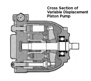 Should more flow be required, the swash plate angle changes, increasing the pump displacement by creating a longer piston stroke. Contrary to a fixed displacement piston pump, the variable displacement is used in a closed center system. With a closed center system, the swash plate angle within the variable displacement pump decreases as the flow requirement diminishes so that there is no excess flow or loss of hydraulic horsepower.
Variable displacement piston pumps can be flow compensated, pressure compensated, or both flow and pressure compensated.
Flow Compensated: As flow requirements change, the swash plate angle is adjusted to maintain a constant margin of pressure.
Pressure Compensated: Regardless of changes in system pressure, a specified flow is maintained by adjusting the swash plate angle.
Flow and Pressure Compensated Combined: These systems with flow and pressure compensation combined are often called a load-sensing system, which is common for snow and ice control vehicles.
 VANE PUMPS
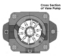
Vane pumps were, at one time, commonly used on utility vehicles such as aerial buckets and ladders. Today, the vane pump is not commonly found on these mobile truck-mounted hydraulic systems as gear pumps are more widely accepted and available.
Within a vane pump, as the input shaft rotates it causes oil to be picked up between the vanes of the pump which is then transported to the pump’s outlet side. This is similar to how gear pumps work, but there is one set of vanes—versus a pair of gears—on a rotating cartridge in the pump housing. As the area between the vanes decreases on the outlet side and increases on the inlet side of the pump, oil is drawn in through the supply port and expelled through the outlet as the vane cartridge rotates due to the change in area.
QUICK LOOK
- Used on utility vehicles, but not as common today with gear pumps more widely accepted and available
- Input shaft rotates, causing oil to be picked up between the vanes of the pump which is then transported to the pump outlet side as the area between vanes decreases on the outlet side and increases on the inlet side to draw oil through the supply port and expel through outlet as vane cartridge rotates
Muncie Power does not offer vane pumps.
 CLUTCH PUMPS
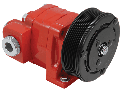
A clutch pump is a small displacement gear pump equipped with a belt-driven, electromagnetic clutch, much like that found on a car’s air conditioner compressor. It is engaged when the operator turns on a switch inside the truck cab. Clutch pumps are frequently used where a transmission power take-off aperture is not provided or is not easily accessible. Common applications include aerial bucket trucks, wreckers, and hay spikes. As a general rule, clutch pumps cannot be used where pump output flows are more than 15 GPM as the engine drive belt is subject to slipping under higher loads.
QUICK LOOK
- Small displacement pumps
- Belt driven
- Aerial bucket trucks, wreckers, and hay spikes
- Limited to 15 GPM applications
DUMP PUMPS
 Of the different types of hydraulic pumps, the dump pump is the most recognizable. This type of pump is commonly used in dumping applications from dump trailers to tandem axle dump trucks. The dump pump is specifically designed for one application—dump trucks—and is not suitable for other common trailer applications such as live floor and ejector trailers.
What separates this pump from the traditional gear pump is its built-in pressure relief assembly and an integral three-position, three-way directional control valve. The dump pump is unsuited for continuous-duty applications because of its narrow, internal paths and the subsequent likelihood of excessive heat generation.
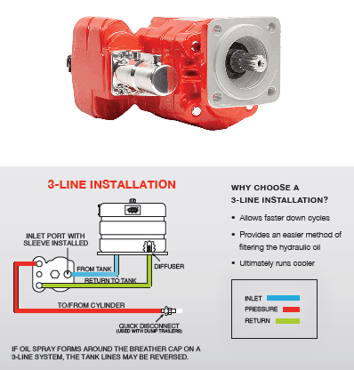
Dump pumps are often direct mounted to the power take-off; however, it is vital that the direct-coupled pumps be rigidly supported with an installer-supplied bracket to the transmission case with the pump’s weight at 70 lbs. With a dump pump, either a two- or three-line installation must be selected (two-line and three-line refer to the number of hoses used to plumb the pump); however, a dump pump can easily be converted from a two- to a three-line installation. This is accomplished by inserting an inexpensive sleeve into the pump’s inlet port and uncapping the return port.
Many dump bodies can function adequately with a two-line installation if not left operating too long in neutral. When left operating in neutral for too long, however, the most common dump pump failure occurs due to high temperatures. To prevent this failure, a three-line installation can be selected—which also provides additional benefits.
QUICK LOOK
There are typically three types of hydraulic pump constructions found in mobile hydraulic applications. These include gear, piston, and vane; however, there are also clutch pumps, dump pumps, and pumps for refuse vehicles such as dry valve pumps and Muncie Power Products’ Live PakTM.
The hydraulic pump is the component of the hydraulic system that takes mechanical energy and converts it into fluid energy in the form of oil flow. This mechanical energy is taken from what is called the prime mover (a turning force) such as the power take-off or directly from the truck engine.
With each hydraulic pump, the pump will be of either a uni-rotational or bi-rotational design. As its name implies, a uni-rotational pump is designed to operate in one direction of shaft rotation. On the other hand, a bi-rotational pump has the ability to operate in either direction.
GEAR PUMPS
For truck-mounted hydraulic systems, the most common design in use is the gear pump. This design is characterized as having fewer moving parts, being easy to service, more tolerant of contamination than other designs, and being relatively inexpensive. Gear pumps are fixed displacement, also called positive displacement, pumps. This means the same volume of flow is produced with each rotation of the pump’s shaft. Gear pumps are rated in terms of the pump’s maximum pressure rating, cubic inch displacement, and maximum input speed limitation.
Generally, gear pumps are used in open center hydraulic systems. Gear pumps trap oil in the areas between the teeth of the pump’s two gears and the body of the pump, transport it around the circumference of the gear cavity, and then force it through the outlet port as the gears mesh. Behind the brass alloy thrust plates, or wear plates, a small amount of pressurized oil pushes the plates tightly against the gear ends to improve pump efficiency.
QUICK LOOK
- Most common design
- Fewer moving parts, easy to service, more tolerant of contaminants, relatively inexpensive
- Fixed, also called positive displacement pumps
- Rated in terms of maximum pressure rating, cubic inch displacement, maximum input speed limitation
- Used in open center hydraulic systems
- Transports oil around the circumference of the gear cavity and forces it through the outlet port
- Encompasses thrust plates that push against gear ends with a small amount of pressurized oil to improve pump efficiency
PISTON PUMPS
When high operating pressures are required, piston pumps are often used. Piston pumps will traditionally withstand higher pressures than gear pumps with comparable displacements; however, there is a higher initial cost associated with piston pumps as well as a lower resistance to contamination and increased complexity. This complexity falls to the equipment designer and service technician to understand to ensure the piston pump is working correctly with its additional moving parts, stricter filtration requirements, and closer tolerances. Piston pumps are often used with truck-mounted cranes, but are also found within other applications such as snow and ice control where it may be desirable to vary system flow without varying engine speed.
A cylinder block containing pistons that move in and out is housed within a piston pump. It’s the movement of these pistons that draw oil from the supply port and then force it through the outlet. The angle of the swash plate, which the slipper end of the piston rides against, determines the length of the piston’s stroke. While the swash plate remains stationary, the cylinder block, encompassing the pistons, rotates with the pump’s input shaft. The pump displacement is then determined by the total volume of the pump’s cylinders. Fixed and variable displacement designs are both available.
QUICK LOOK
- Withstand higher pressures
- Higher initial cost, lower resistance to contamination, and increased complexity
- Additional moving parts, stricter filtration requirements, and closer tolerances
- Truck-mounted cranes
- Good when desirable to vary system flow without varying engine speed
- Fixed and variable displacement designs available
- Encompasses cylinder block containing pistons that move in and out—this movement draws oil from the supply port and forces through the outlet
- The angle of the swash plate determines the length of the piston’s stroke
- Swash plate remains stationary
- Displacement determined by the total volume of pump cylinders
FIXED DISPLACEMENT
With a fixed displacement piston pump, the swash plate is nonadjustable. Its proportional output flow to input shaft speed is like that of a gear pump and like a gear pump, the fixed displacement piston pump is used within open center hydraulic systems.
VARIABLE DISPLACEMENT
As previously mentioned, piston pumps are also used within applications like snow and ice control where it may be desirable to vary system flow without varying engine speed. This is where the variable displacement piston pump comes into play—when the hydraulic flow requirements will vary based on operating conditions. Unlike the fixed displacement design, the swash plate is not fixed and its angle can be adjusted by a pressure signal from the directional valve via a compensator.
Should more flow be required, the swash plate angle changes, increasing the pump displacement by creating a longer piston stroke. Contrary to a fixed displacement piston pump, the variable displacement is used in a closed center system. With a closed center system, the swash plate angle within the variable displacement pump decreases as the flow requirement diminishes so that there is no excess flow or loss of hydraulic horsepower.
Variable displacement piston pumps can be flow compensated, pressure compensated, or both flow and pressure compensated.
Flow Compensated: As flow requirements change, the swash plate angle is adjusted to maintain a constant margin of pressure.
Pressure Compensated: Regardless of changes in system pressure, a specified flow is maintained by adjusting the swash plate angle.
Flow and Pressure Compensated Combined: These systems with flow and pressure compensation combined are often called a load-sensing system, which is common for snow and ice control vehicles.
VANE PUMPS
Vane pumps were, at one time, commonly used on utility vehicles such as aerial buckets and ladders. Today, the vane pump is not commonly found on these mobile truck-mounted hydraulic systems as gear pumps are more widely accepted and available.
Within a vane pump, as the input shaft rotates it causes oil to be picked up between the vanes of the pump which is then transported to the pump’s outlet side. This is similar to how gear pumps work, but there is one set of vanes—versus a pair of gears—on a rotating cartridge in the pump housing. As the area between the vanes decreases on the outlet side and increases on the inlet side of the pump, oil is drawn in through the supply port and expelled through the outlet as the vane cartridge rotates due to the change in area.
QUICK LOOK
- Used on utility vehicles, but not as common today with gear pumps more widely accepted and available
- Input shaft rotates, causing oil to be picked up between the vanes of the pump which is then transported to the pump outlet side as the area between vanes decreases on the outlet side and increases on the inlet side to draw oil through the supply port and expel through outlet as vane cartridge rotates
Muncie Power does not offer vane pumps.
CLUTCH PUMPS
A clutch pump is a small displacement gear pump equipped with a belt-driven, electromagnetic clutch, much like that found on a car’s air conditioner compressor. It is engaged when the operator turns on a switch inside the truck cab. Clutch pumps are frequently used where a transmission power take-off aperture is not provided or is not easily accessible. Common applications include aerial bucket trucks, wreckers, and hay spikes. As a general rule, clutch pumps cannot be used where pump output flows are more than 15 GPM as the engine drive belt is subject to slipping under higher loads.
QUICK LOOK
- Small displacement pumps
- Belt driven
- Aerial bucket trucks, wreckers, and hay spikes
- Limited to 15 GPM applications
DUMP PUMPS
Of the different types of hydraulic pumps, the dump pump is the most recognizable. This type of pump is commonly used in dumping applications from dump trailers to tandem axle dump trucks. The dump pump is specifically designed for one application—dump trucks—and is not suitable for other common trailer applications such as live floor and ejector trailers.
What separates this pump from the traditional gear pump is its built-in pressure relief assembly and an integral three-position, three-way directional control valve. The dump pump is unsuited for continuous-duty applications because of its narrow, internal paths and the subsequent likelihood of excessive heat generation.
Dump pumps are often direct mounted to the power take-off; however, it is vital that the direct-coupled pumps be rigidly supported with an installer-supplied bracket to the transmission case with the pump’s weight at 70 lbs. With a dump pump, either a two- or three-line installation must be selected (two-line and three-line refer to the number of hoses used to plumb the pump); however, a dump pump can easily be converted from a two- to a three-line installation. This is accomplished by inserting an inexpensive sleeve into the pump’s inlet port and uncapping the return port.
Many dump bodies can function adequately with a two-line installation if not left operating too long in neutral. When left operating in neutral for too long, however, the most common dump pump failure occurs due to high temperatures. To prevent this failure, a three-line installation can be selected—which also provides additional benefits.
QUICK LOOK
- Specifically designed for dump trucks
- Displacement of slightly more than six cubic inches, pressure relief assembly, and integral three-position, three-way directional control valve
- Not suited for continuous-duty applications
- Often direct mounted to power take-off, need installer-supplied bracket to support
- Two- and three-line installations available (two-line can be converted to three-line)